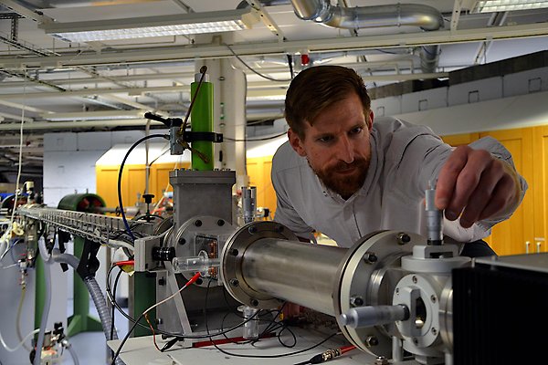
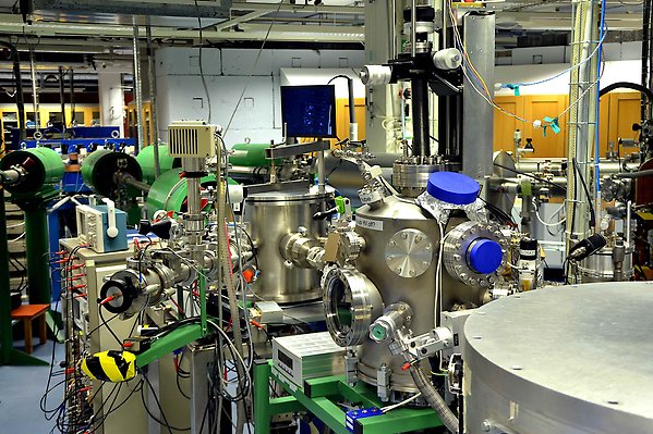
5 MeV Tandem accelerator
The 5 MV 15SDH-2 Tandem Pelletron accelerator from NEC is the largest accelerator at the Tandem Laboratory. Four dedicated sources produce a broad range of light and heavy ion species with energies between 2 MeV to several 10 MeV. The Tandem accelerator supplies ions to six different beamlines, enabling the machine’s use for a number of different techniques within ion beam analysis and ion beam modification of materials.
Beamline 1: Nuclear reaction analysis set-up
Beamline 2: The Uppsala scanning nuclear microprobe
Beamline 3: The new LigHt platform is being built here
Beamline 4: Comprehensive ion beam materials analysis
Beamline 5: MeV ion irradiations
Beamline 6: In-situ growth, modification and ion beam analysis
Features
- One duaplasmatron source dedicated to the production of helium isotopes.
- One duaplasmatron, also using gas as initial material, providing beams of for example protons, deuterons or nitrogen isotopes.
- Two Cs sputter sources using solid targets. Examples of ions produced by these sources, which are regularly used in our laboratory, are: ⁶Li, ⁷Li, ¹²C, ¹⁶O, ¹⁹F, ³¹P, ³⁵Cl, ⁷⁴Ge, ⁷⁹Br, ¹⁰⁷Ag, ¹²⁷I and Au.
- Two-stage acceleration: initially negative ions are accelerated towards the high-voltage terminal where (some of) their electrons are removed in a gas cell. The now positive ions are accelerated again upon exiting the terminal.
- Upper energy limit of about 50 MeV for heavy ions depending on the maximum achievable charge state when stripping inside the gas cell.
- Additional stripping stage behind the accelerator allowing for charge states up to at least 25+ without further changing the ion energy.
Beamline 1: Nuclear reaction analysis set-up
This beamline features one end station that is primarily used for measuring hydrogen concentration with high depth resolution. At an energy of 6.385 MeV, the nitrogen isotope ¹⁵N undergoes a resonant nuclear reaction (link to internal method site) with hydrogen (¹⁵N(H,αγ)¹²C ) leading to the emission of a characteristic gamma photon with an energy of 4.43 MeV. The set-up is equipped with a gamma detector to record these photons, enabling hydrogen quantification. Making use of the characteristic energy loss of the ions in a sample, increasing the incident beam energy step-by-step allows for measurements of hydrogen depth profiles with a resolution of a few nanometres.
The sample is mounted to a goniometer allowing for angle-resolved measurements and ion channelling experiments. As an example, the position of hydrogen atoms stored in Fe/V superlattices could be determined in this way.
The chamber also holds a particle detector that can be operated simultaneously with the gamma detector for RBS and EBS analysis.
Interstitial Hydrogen in Fe/V Superstructures: Lattice Site Location and Thermal Vibration
Part of Physical Review Letters, 2021
- DOI for Interstitial Hydrogen in Fe/V Superstructures: Lattice Site Location and Thermal Vibration
- Download full text (pdf) of Interstitial Hydrogen in Fe/V Superstructures: Lattice Site Location and Thermal Vibration

Features
- Lead-shielded bismuth germanate scintillation detector for gamma ray detection, covering a solid angle of 1 sr.
- Passivated implanted planar silicon detector (PIPS) for RBS and EBS measurements.
- Automatic recording of data for different beam energies for convenient determination of depth profiles.
- Automatized goniometer motion, including one rotational axis perpendicular to the beam direction.
- Thermal contact to an outside reservoir allowing for modification of the sample temperature between liquid nitrogen temperature and ~90°C.
- Base pressure inside the chamber: ~10‾⁸ mbar.
To additionally analyse the lateral distribution of chemical elements in a sample, the ion beam is focussed down to the micrometre scale and scanned across the sample surface. Our scanning light ion microprobe uses proton or helium beams from the Tandem accelerator and focusses them into a target chamber featuring several detectors.
A spot size down to 1.5 µm x 1.0 µm can be achieved. For high-current applications, with ion currents reaching several hundred pA, an excellent spot size of 3.3 µm x 2.0 µm is still possible. The largest area that can be scanned by the beam is about 2 mm x 2 mm, however, larger maps can be generated by an automated combination of beam scanning and sample holder movement.
Several ion beam analysis methods can be combined with the microbeam. PIXE, RBS, STIM, ERDA and NRA are implemented and used during daily operation. Digital image processing techniques can be performed on recorded IBA maps to automatically identify and analyse individual micrometre-sized particles.
The microprobe is a very versatile tool that can be employed in many different research areas. Recent examples include a study on ink deposition relevant for forensics and depth-resolved elemental mapping of individual metal-organic framework (MOF) crystals with applications in catalysis.
The scanning light ion microprobe in Uppsala - Status in 2022
Part of Nuclear Instruments and Methods in Physics Research Section B, p. 66-69, 2022
- DOI for The scanning light ion microprobe in Uppsala - Status in 2022
- Download full text (pdf) of The scanning light ion microprobe in Uppsala - Status in 2022
Part of Journal of the American Chemical Society, p. 18626-18634, 2021
- DOI for Elemental Depth Profiling of Intact Metal-Organic Framework Single Crystals by Scanning Nuclear Microprobe
- Download full text (pdf) of Elemental Depth Profiling of Intact Metal-Organic Framework Single Crystals by Scanning Nuclear Microprobe
Part of Journal of Forensic Sciences, p. 1401-1409, 2021
- DOI for Determining the chronological sequence of inks deposited with different writing and printing tools using ion beam analysis
- Download full text (pdf) of Determining the chronological sequence of inks deposited with different writing and printing tools using ion beam analysis
Features
- Microprobe elements from Oxford Microprobe Ltd., including collimator apertures, a triplet of magnetic quadrupole focussing lenses and dipole coils for raster scanning.
- Annular surface barrier detector (thickness: 1500 µm, solid angle: 0.39 sr) for RBS/EBS and NRA analysis.
- Retractable, liquid nitrogen cooled Si(Li) detector with 30 mm² active area for PIXE analysis.
- PIN diode detectors for ERDA and STIM measurements. The unit is movable allowing for on-axis and off-axis
- Optical microscope within the target chamber.
- Electric isolation of the target chamber from the beamline and support structures for measurements of the beam current. Additionally, the beam current can be measured at the sample holder and, in case of sufficiently thin samples, with a Faraday cup installed in transmission geometry.
This beamline features two chambers that constitute the workhorses for ion beam analysis (IBA) measurements at the Tandem Laboratory. The possibility to run several IBA methods at the same time, gives users complimentary information and allows for comprehensive materials characterisation. This multi-method approach has been exemplarily demonstrated for transition-metal alloys.
The first chamber is dedicated to high-throughput IBA experiments including RBS, EBS, NRA, PIXE, and ToF-ERDA. 20 samples can be mounted on the same holder and run in an automated fashion. The sample holder can be tilted around two axes allowing for ion channelling experiments.
The second chamber is mostly dedicated to ToF-ERDA measurements with a gas ionisation chamber installed to measure the energy. This technique leads to improved mass resolution and lower susceptibility to radiation damage than a solid-state detector as employed in the first chamber. The latter feature makes this detection technique suitable to even analyse samples containing elements with high atomic number. The set-up is complemented by a PIXE detector, particle detectors for other IBA techniques as well as feedthroughs for electrical signals. The vacuum chamber is designed to accommodate relatively large samples with sizes up to 20 cm x 15 cm with a thickness of several cm. Even larger samples may be installed with limited capacities for movement. Recently, this set-up has been employed to observe changes in lithium and oxygen distributions within a thin film lithium-ion battery while charging and discharging.
An additional third chamber leaves space for the creation of custom set-ups and demonstration experiments, used for example in student education.
Part of Review of Scientific Instruments, 2016
Part of Thin Solid Films, 2019
In-operando observation of Li depth distribution and Li transport in thin film Li ion batteries
Part of Applied Physics Letters, 2020
Features first chamber
- One passivated implanted planar silicon (PIPS) detector fixed at 170° scattering angle, and a second one freely movable for various IBA techniques. More detectors can be installed on demand, and by adding their individual signals the effective solid angle of the experiment can be increased.
- ToF-ERDA set-up to measure energy and flight time in coincidence. It consists of a solid-state detector for energy measurement at the end of a time-of-flight stage using two carbon foils.
- Amptek XR-100 Si drift detectors for PIXE measurements.
- Automated sample movement including randomised, small-angle tilting around a fixed scattering angle to avoid channelling and blocking effects.
Features second chamber
- ToF-ERDA detector using a gas ionization chamber instead of a solid-state detector for improved mass resolution and decreased susception to radiation damage.
- Active pumping of the time-of-flight set-up even during standby, thereby minimising variations in detection efficiency.
- Amptek XR-100 Si drift detectors for PIXE measurements.
- Large viewports for optical characterisation and manipulation.
- Sample movement by 20 cm along the vertical axis, and 3 cm along the two perpendicular axes possible. The sample can be rotated freely around the vertical axis.
Beamline 5: MeV ion irradiations
Irradiations with energetic ions are used to tailor materials properties or to engineer nanostructures. Ion species, energy and charge state can be selected at the Tandem accelerator in accordance with the desired outcome or application. A deflector pair at the irradiation beamline can scan the ion beam to homogeneously irradiate areas of up to 10 cm x 10 cm. The set-up has been used to investigate defects and vacancies in several semiconductor materials, including nanoparticles, as well as to produce ion tracks in polyimide to study the fabrication of nanomembranes with potential applications in for example biotechnological filtration or gas sensing.
Ion Track Formation and Nanopore Etching in Polyimide: Possibilities in the MeV Ion Energy Regime
Part of Macromolecular materials and engineering, 2023
- DOI for Ion Track Formation and Nanopore Etching in Polyimide: Possibilities in the MeV Ion Energy Regime
- Download full text (pdf) of Ion Track Formation and Nanopore Etching in Polyimide: Possibilities in the MeV Ion Energy Regime
Features
- Ion fluences up to a few times 10¹⁶ per cm² achievable within hours of exposure time.
- Up to 20 samples can be loaded at a time in a load-lock chamber. From there samples are transferred one by one to the irradiation chamber.
- Wafer sizes up to 4'' can be accommodated in standard sample frames.
- Electrical feedthroughs for studying electrical properties during operation.
- Pressure during irradiation: ca. 5 x 10‾⁷ mbar.
Beamline 6: In-situ growth, modification and ion beam analysis
The sixth beamline combines MeV ion beam analysis with possibilities for thin film growth and materials modification to study (near-) surface processes such as the very initial stages of growth or oxidation in-situ. The multipurpose Set-up for In-situ Growth, Materials modification and Analysis by ion beams (SIGMA) is equipped with several tools and detectors to achieve this goal.
A three-source electron-beam evaporator allows growing films from up to three target materials simultaneously. The equipment is complemented by an ion sputter gun and the possibility to introduce gas into the chamber allowing for further modification and reactive growth. Sample annealing or cooling during evaporation or ion beam analysis is possible. The chamber houses several particle detectors as well as detectors for X-rays and gamma rays permitting comprehensive ion beam materials analysis without exposing the grown or prepared samples to air.
Among others, SIGMA has been employed to study the formation of photochromic materials for smart-window applications and to examine microstructure and thermally induced segregation and diffusion in fusion-relevant materials.
SIGMA: A Set-up for In-situ Growth, Material modification and Analysis by ion beams
Part of Nuclear Instruments and Methods in Physics Research Section B, p. 96-100, 2020
Part of Nuclear Materials and Energy, 2023
- DOI for Influence of thermal annealing and of the substrate on sputter-deposited thin films from EUROFER97 on tungsten
- Download full text (pdf) of Influence of thermal annealing and of the substrate on sputter-deposited thin films from EUROFER97 on tungsten
Part of Materialia, 2023
- DOI for In-situ, real-time investigation of the formation of oxygen-containing rare-earth hydrides by combining a quartz crystal microbalance and ion beam analysis
- Download full text (pdf) of In-situ, real-time investigation of the formation of oxygen-containing rare-earth hydrides by combining a quartz crystal microbalance and ion beam analysis
Features
- Three passivated implanted planar silicon particle detectors: one movable in backscattering geometry for RBS, EBS and NRA and two in forward-scattering direction for ERDA.
- X-ray detector for PIXE measurements.
- High-purity germanium detector for detecting gamma rays from nuclear reactions (PIGE and NRA).
- 5-axes goniometer (3 translations, 2 rotations) for precise positioning of the sample.
- Filament at sample backside for resistive and electron-beam heating up to ~1000°C.
- Possibility to cool the sample with liquid nitrogen.
- Triple source electron-beam evaporator (FOCUS EFM 3 T) with three independent cells equipped with filaments, high-voltage supplies and crucibles or rods allowing for deposition of up to three target materials.
- Ion gun providing argon, deuterium or hydrogen ions with energies between 0.12 keV and 5 keV.
- Possibility to use a high-sensitivity quartz crystal microbalance for real-time monitoring of mass changes simultaneous to film growth, ion implantation or ion beam analysis.
- Detachable load-lock-chamber that can be used to transfer samples under high-vacuum conditions.
- Base pressure of the chamber: ~5 x 10‾⁹ mbar.